When a C64 fails, the most common symptom is a black screen. While having a display of some sorts makes troubleshooting easier, a black screen gives away many useful hints. Here is how I usually start the diagnostics process, when I get a machine with a black screen.
Tools and preparations
Before we start, let’s be clear that a black screen can be caused by just about any component on the mainboard. It is hardly possible to provide a complete guide on how to troubleshoot from that starting point, but rather to provide guidance on how to perform the initial steps in the diagnostics process and hopefully get closer to either solving the problem or isolating it.
I often buy machines sold as defective only to discover that the problem was something completely trivial, which could be fixed by anoyone with the right knowledge.
Before we start, it should be obvious that you won’t make much progress without a minmum set of tools.
First and foremost, it makes absolutely no sense to try troubleshooting anything without on a C64 without a known working power supply and a known working monitor + cable.
Second, to get any sort of information out or a machine with a black screen, you will need the following as a minimum:
- Dead Test Cartridge or even better a DesTestMAX cartridge.
- A multimeter
- A valid way of testing chips:
- A test board with all ICs in sockets
- A chiptester. This could be the BackBit Chip Tester or a Retro Chip Tester Pro.
Additional tools like soldering iron and desoldering station may become handy as well.
Check removable parts outside the board
The first thing I do is to remove all socketed chips and test them outside the defective board. If socketed, the SID, ROMs and CIAs should be left out of the board during the rest of the procedure. They are not required and there is no point it risking anything.
Voltages and fuse check
While in the basic department, the next step is to check that the voltages and the fuse are okay. A C64 power supply provides two power inputs:
- 9V AC (when measured directly on the PSU connector, expect 10V AC
- 5V DC (expect somewhere between 5V and 5.3V on a normal, healthy PSU without load
You shouldcheck that the power inputs make it past the power switch, as it is a likely culprit for a lot of things.
On the user port, 9V AC should be present between pins 10 and 11 and 5V DC should be available between pins 1 (GND) and 2 (+5V). If you miss either power rail on the user port, test direcly on the power switch to ensure that it is working. If not, the power switch or the power connector are bad.
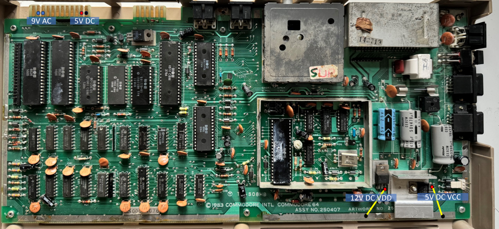
Provided that you got the expected power measurements at the userport, the next thing to check is that the power rails generated internally from the 9V AC rail, are present on the board.
On the longboards, 9V AC is transformed into two separate tails:
- 12V DC. In the service manual, the 9V/12V DC rail is referred to as VDD.
- 5V DC rail referred to as CAN or VCC.
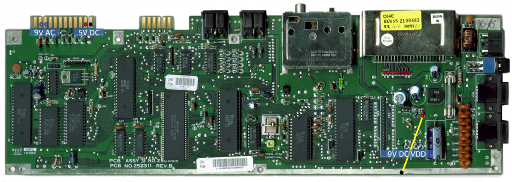
On a shortboardboard, 9V AC is transformed into 9V DC by a bridge rectifier. The 5V rail for the A/V and clock circuits is taken directly from the external power supply.
On the longboards, VDD and VCC are used by the VIC, SID and clock circuits only. Unlike the regular 5V rail (VDC), VDD and VCC are protected by the fuse, meaning that if the fuse dies, only the 9/12 VDD and 5 VCC will disappear.
If you don’t see VDD and VCC, check the fuse for continuity.
On a shortboard, a dead fuse will allow the machine to work except for the sound.
The illustrations provice guidance on voltage measurements. The dots indicate where to put the multimeter probes. Ground is many places on the board, so you don’t necessarily have to put the black probes on the edge. It can be the shield for the cartridge port or the RF modulator as well.
The image below indicates where to measure on a shortboard:
Video output?
So, voltages are good and the fuse is good. Now what?
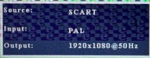
When troubleshooting, I always connect the computer through my upscaler. As seen on the picture below, the upscaler generates an overlay showing source, input and output. Notably we see that it has detected a PAL input. This is an important finding, as the C64 needs a working VIC II, a working clocl circuit / 8701 Clock generator and a working RF modulator to generate a PAL signal. Hence, the below indicates that all these are good. And with that information, we can more or less focus on the left side of the board, provided we are working on a longboard.
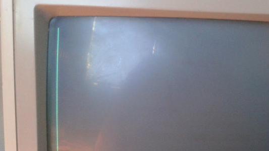
If you don’t have an upscaler with similar features, a CRT monitor may be just as useful as it should generate a white line to the far left of the screen, provided you have the entire picture visible. A white line means that you have a PAL sync signal.
If there is no PAL sync signal, the immediate suspects are the VIC II and the MOS 8701 if present. If they turn out to work, the crystal and the RF modulator are next in line.
Dead test
So, you have a working video output. What next?
This is where I turn to my trusty old Deadtest cartridge or the newer DesTestMax. As these cartridges run in hypermax mode, they only rely on very few things to work:
- The CPU
- The PLA
- The VIC II and the video section (which we already established to be working)
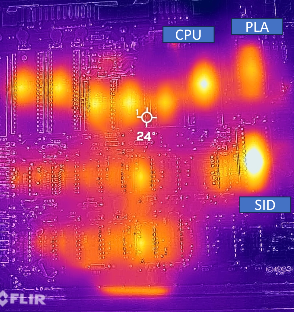
In other words, if neither of those cartridges run (for Dead test, it shouldn’t even produce a flashing screen), this indicates that the CPU or the PLA are faulty. A lof of people will tell you that the PLA is among the most error-prone parts on a C64 longboard. While that is true, it is worth noting that the CPU gets even warmer even though that is nothing comparted to the SID.
If, on the other hand, youe Dead test / DesTestMax cartirdge runs, the CPU and PLA are likely to work, and you should start focusing on RAM, logic, ROMs (particularly the kernal) and CIAs if still present on the board.
Beyond the basics
Let’s assume that you made it to the point where you have established that the video section is working. What next?
If DeadTest makes it to the point where it displays text on the screen, you should suspect the kernal or another ROM chip.
If DeadTest boots with white flashes, this indicates a data line problem, which may be caused by a bad RAM chip, but could be caused by any part communicating on the databus.
Quite often, this is where things turn complicated, and you may find yourself doing some trial and error trouble shooting.
In my experience, it pays off to start the rest of your search by looking at the brand of chips used on the particular board. If the RAM is mT branded, that immediately raises the suspecion that you have a RAM problem. If any of the logic chips are MOS-branded, that’s an qually good indicator of where to start.
Leave a Reply